Aerospace & Mechanical Engineering · CWRU Class of 2029
Mechanical and Aerospace Engineering student at Case Western Reserve University (Class of 2029) with a strong interest in drones, aircraft, robotics, and their defense applications. Experienced with SolidWorks and ANSYS for CAD, simulation, and engineering analysis through personal and team projects. Varsity Track & Field and Cross Country athlete with a proven commitment to teamwork, discipline, and continuous improvement.
Skills
Computer-Aided Design
My primary design environment is SolidWorks, where I develop parametric models with a focus on efficiency, precision, and manufacturability. I build parts driven by global variables so designs can be rapidly iterated without compromising assembly integrity. I've designed everything from drone frames and motor mounts to payload release mechanisms and precision fabrication jigs. I also use SolidWorks PDM for version control on team projects and am comfortable working across part, assembly, and drawing workflows. I genuinely enjoy mechanical design and continuously seek opportunities to expand my CAD skills and engineering knowledge.
Simulation & Analysis
For engineering simulations, I primarily use SolidWorks Simulation and ANSYS. In SolidWorks, I perform finite element analysis (FEA) to validate designs under realistic load cases, such as verifying that drone arms can withstand motor-induced forces while minimizing weight. For aerodynamics, I use SolidWorks Flow Simulation to evaluate and optimize different geometries, reducing drag in high-speed designs through iterative analysis. I have also expanded my simulation capabilities by learning ANSYS for advanced aerodynamic and heat transfer analysis.
Fabrication & Manufacturing
I really enjoy fabrication and machining and take every opportunity to build and test my designs. I've worked with CNC waterjets for precision metal cutting, mills and lathes to machine steel and aluminum components, and both MIG and TIG welding for structural assemblies. On the additive manufacturing side, I use FDM 3D printing for rapid prototyping as well as functional end-use parts, including the shell for my high-speed drone. I've also worked with CNC laser cutters, plastic thermoforming, and CNC milling to manufacture precision components.
Electronics & Programming
I've been coding for 5+ years and have always enjoyed using software to solve engineering problems. My strongest languages are Python, Java, and MATLAB, and I have written flight control software in Arduino, including a hand-tuned PID controller for one of my drones. On the electronics side, I have experience sourcing components, performing fine-pitch soldering, and developing custom PCB designs. I have a strong understanding of programming fundamentals and am comfortable learning new languages, frameworks, and tools as project requirements evolve.
Projects
Hardware, software, and everything in between. Click any project to open the full breakdown.
Aerospace / CAD · 2025 – Present
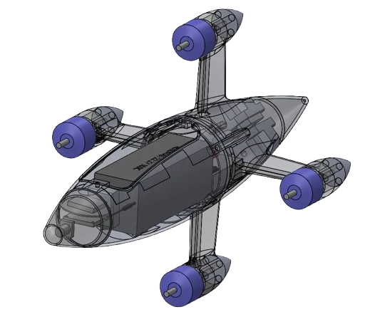
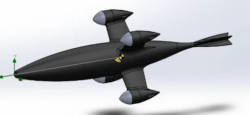
Led a team of engineers to build the fastest quadcopter possible. Parametric NACA-profile shell and arm design, CFD-driven drag and stability optimization, FEA-validated material selection, and full electronics BoM management.
↗ Click for full details
Mechanical Design · 2026 — 3rd Place
Designed a permanent magnet payload dropper with a servo-driven release mechanism and redundant magnet array for reliable payload retention. After the original 3D-printed landing gear became unstable and loosened during field testing, I redesigned and fabricated a stronger aluminum landing gear system to improve durability and reliability. Achieved a third-place finish out of 20 teams at the championship.
↗ Click for full details
Hardware / Embedded · Dec 2025 – Feb 2026
A quadcopter built completely from the ground up, from the frame to the flight software. Designed and printed a SolidWorks frame, hand-soldered a custom N-channel MOSFET motor driver, built a wireless IMU link over ESP-NOW, and hand-tuned the PID controller that keeps it stable in the air.
↗ Click for full details
Robotics / Biomechanics · Nov 2025
A robotic hand built with a teammate in a two-day CWRU hackathon, designed to open and close from real muscle activity instead of a manual switch. SolidWorks fingers on hinge mates, a MyoWare EMG sensor with a hand-tuned threshold, and a wireless ESP-NOW link driving the servos.
↗ Click for full details
Gallery
The build process, competition moments, and finished hardware.
Contact
Open to internships, research collaborations, and interesting build projects.
Photo
No image added yet
Description
Aerospace / CAD · 2025 – Present
Aerodynamics & Simulations
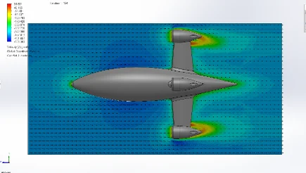
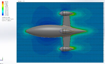
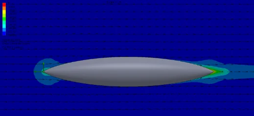
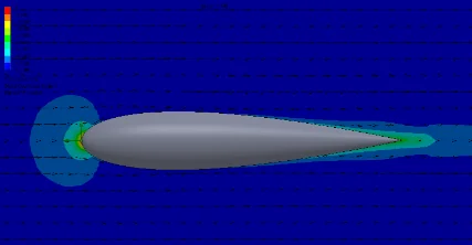
Aero design was the area I learned the most in, largely because it demanded constant iteration. I had never used SolidWorks Flow Simulation before this project, so early on I focused on learning how to set up a proper domain, mesh it correctly, and produce reliable results. Once that workflow was solid, one of my first major design decisions was adding motor caps to the simulation instead of leaving the motors fully exposed, since the bare motor cans were creating separated flow and adding unnecessary drag.
Simulation: No motor caps
Simulation: Motor caps
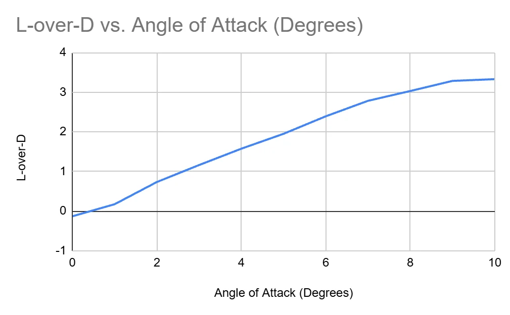
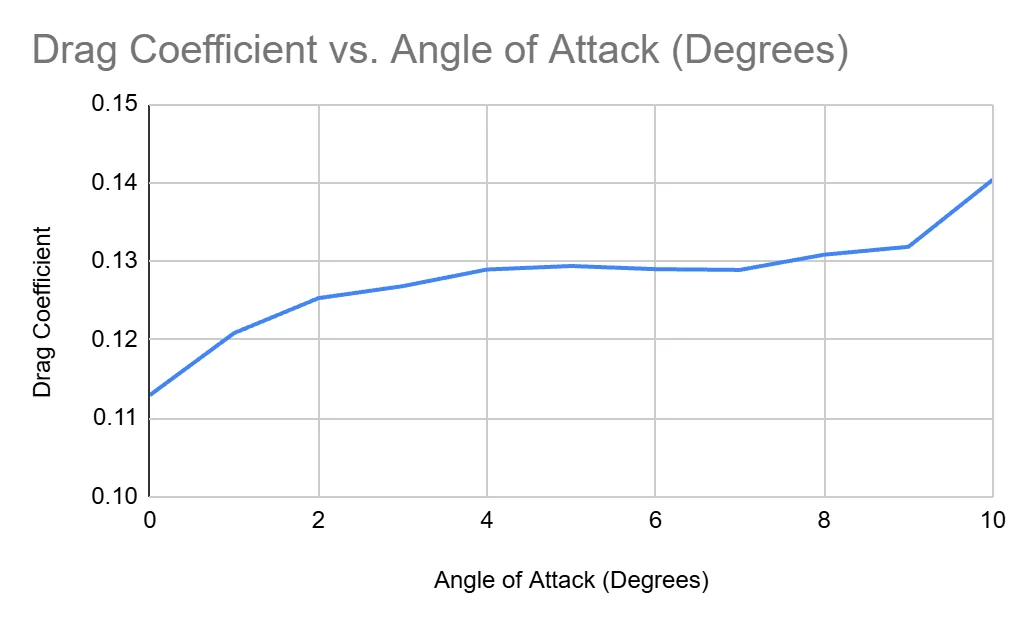
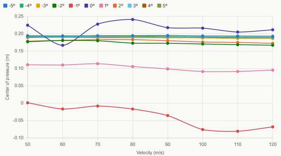
From there I ran parametric simulations sweeping both angle of attack and velocity to understand how lift and drag changed across a realistic flight envelope rather than at a single condition.
This led me to compare center of pressure against center of mass, since having the center of pressure behind the center of mass is the basic condition for passive aerodynamic stability: if the body is disturbed, it tends to correct itself rather than diverge further. To push the center of pressure further back, I shifted the arms forward (a 3% increase in CoP) on the frame and added small fins near the tail (a 2.2% increase in CoP), both of which add surface area and force behind the center of mass. I also found that angle of attack shifts the center of pressure, so stability became less about hitting one fixed value and more about maintaining passive stability across the full range of conditions I cared about.
Originally I designed with the goal of generating enough lift to maintain altitude independently, but I later concluded that goal wasn't particularly useful, since the drone descending isn't a problem as long as it stays stable and controllable. I shifted focus away from lift generation and toward drag reduction and stability instead.
In V2, I began using parametric curves and global variables in SolidWorks so I could run studies across many shell and arm geometries without rebuilding the model each time. Both the shell and arms are based on a NACA 00XX profile: the shell is that profile rotated as a body of revolution, and the arms use the same profile family in cross section. I also spent significant time designing the motor nacelles, since their shape controls how clean the airflow stays around the motor and how much of the motor remains exposed to the airstream. Getting this geometry right proved just as important as the main shell shape. For comparison, I tested my original hand-drawn spline shell against a Sears-Haack body and against the NACA 00XX rotated shell, using data from earlier drag simulations. The Sears-Haack body produced more skin friction drag than the NACA 00XX shell, which wasn't what I expected given that Sears-Haack is typically cited as a minimum-drag shape — this makes sense once you account for the fact that Sears-Haack minimizes wave drag specifically, not skin friction drag at the speeds this drone actually flies at.
Sears-Haack Body
NACA 0016 Body
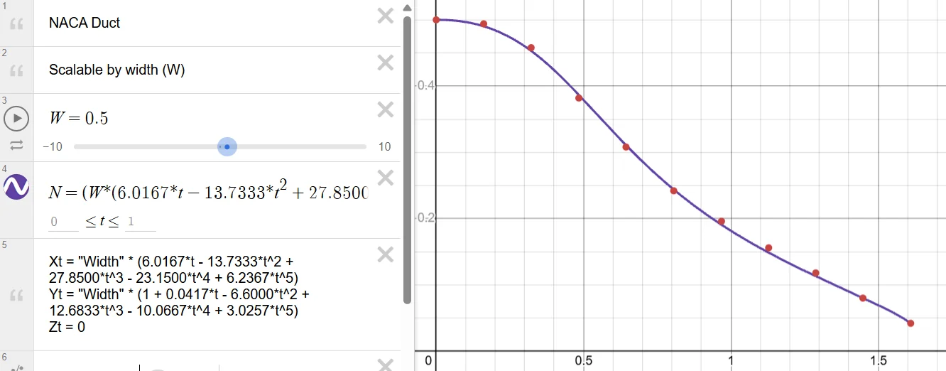
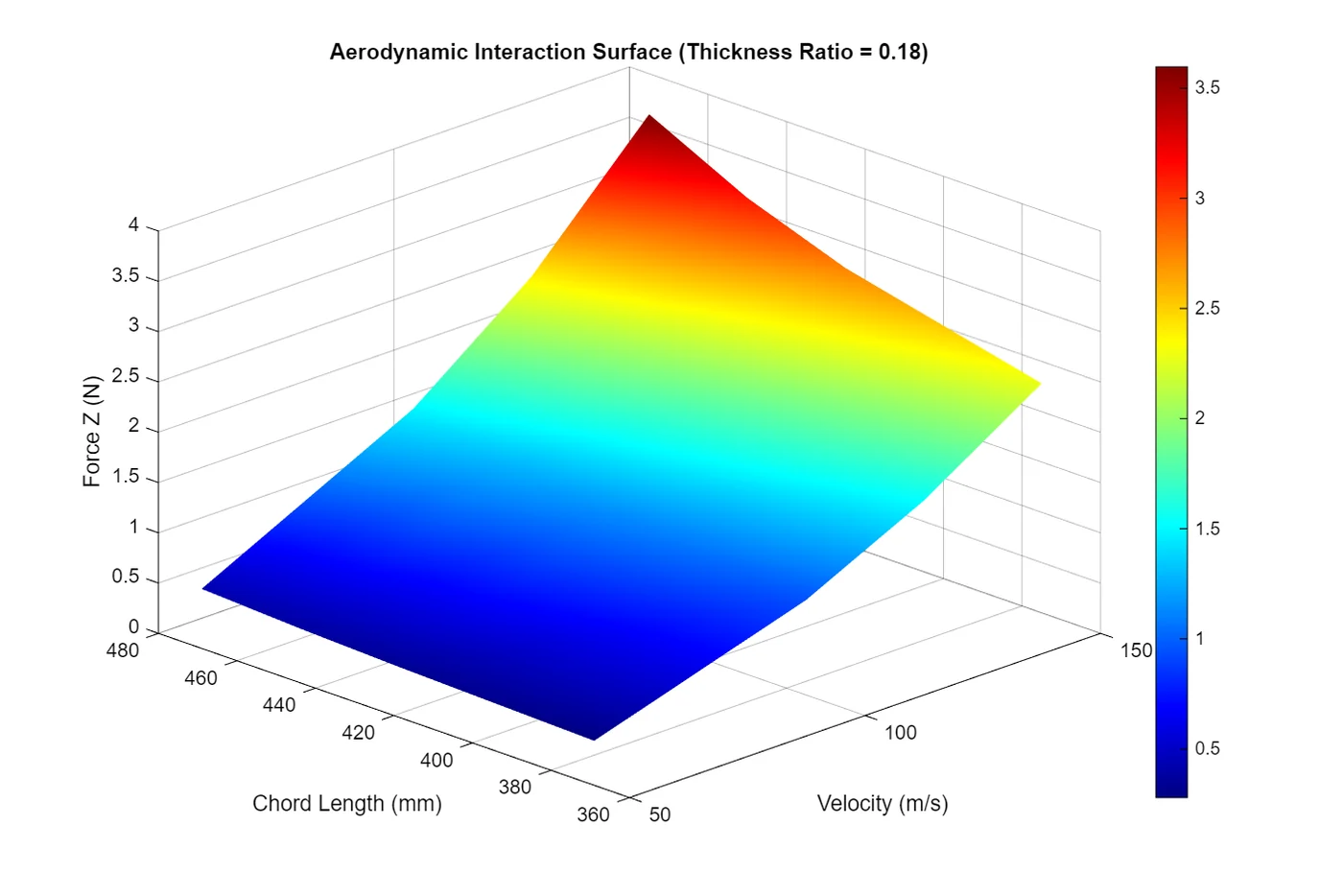
To analyze the parametric data systematically rather than reviewing spreadsheets manually, I wrote a MATLAB script to plot and compare results across the different bodies. I also added a NACA duct, which I derived a parametric equation for in Desmos, to the shell to bring in cooling air and vent it out the tail — specifically to cool the ESCs — and ran simulations to confirm the duct wasn't adding more drag than the cooling benefit justified.
Finite Element Analysis
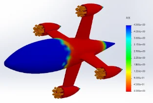
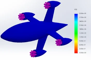
For the structural analysis, I ran static FEA in SolidWorks Simulation to determine the appropriate shell material. The primary metric was factor of safety: the margin between the maximum stress the part experiences and the point at which the material fails. I set a minimum threshold the part needed to meet before I would consider a material acceptable. To interpret these results, I applied concepts from Chemistry of Materials. Von Mises stress reduces a complex three-dimensional stress state to a single equivalent value that can be compared directly against a material's yield strength. Strain describes how much the material deforms, elastically or plastically, under that stress. Displacement is the physical movement of the geometry under load. Running PETG and carbon-fiber-reinforced nylon through the same load case let me directly compare how each material performed and select the one that held up under the required conditions.
PETG
CF Reinforced Nylon
Design Process
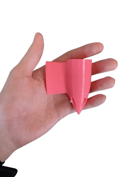
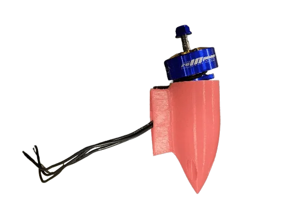
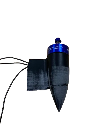
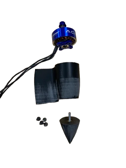
For most of the design, there wasn't too much iteration, but for the arms and motor attachments I had to test a bunch of configurations to make sure the wires could slide through easily, the motor was in the proper position and secure, and the arm was strong enough. I printed four or five versions, making changes until I was finally happy enough with the arms to print the full shell — and because of all that testing, no changes were needed on the full print.
Version 1: wires didn't fit easily, the rotor rubbed, and the screw attachment holes slightly increased drag.
Final version: enlarged the wire slot, added a recess for the rotor, and added a screw-on cap that covers the attachment holes while keeping the flow smooth.
Electronics
The V2 electronics list involved optimizing each component category rather than selecting the first viable part. For motors, ESCs, flight controller, battery, and props, I compared the realistic options side by side based on dimensions, mass, mounting method, and notes on reliability or performance, then highlighted the selected components. The AOS Supernova motors were chosen primarily for mounting compatibility and thermal performance in a pusher configuration, which matters given the lack of prop wash over the motors for cooling. For ESCs, I prioritized additional current headroom rather than operating near the rated limit, since running close to capacity at 12S and above increases the risk of failure mid-flight. For the flight controller, I prioritized clean Betaflight performance and a fast loop rate over additional features, which favored smaller, simpler boards over options like the Pixhawk. Battery selection was based on choosing the minimum capacity sufficient for a single high-speed pass while minimizing mass, since extra capacity beyond that point just adds weight. For props, I selected the APC 7x15E, since prop choice was identified early as one of the most significant performance factors at these speeds.
Next Steps
The next phase involves finalizing the electronics selection, since the current list remains a shortlist rather than a confirmed build. After finalizing the motor, ESC, flight controller, and battery, the next step is completing the wiring and moving into test flights, since simulation and bench fitting can only provide limited insight without flight data. I also plan to investigate heat-sinking for select electronics, particularly the ESCs — improved passive cooling or more effective use of the NACA duct airflow could reduce the size of the cooling features currently built into the design, allowing for a further reduction in shell size and drag.

Mechanical Design · 2025 — 3rd Place Championship
Dropper release demo
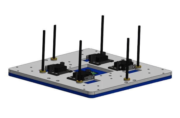
Figuring out how the dropper would actually hold onto and release the payload took a lot of digging into how other teams solve the same problem. I looked at mechanical latches, servo hooks, and a few different magnetic setups before landing on magnetics as the cleanest option. I first built and tested a regular electromagnet: power it on and it holds, cut the power and it drops. It worked fine on the bench, but it only holds as long as it has power, so any brief power hiccup mid flight could drop the payload when I didn't want it to. That was a dealbreaker for something carrying real weight, so I switched to permanent magnets with servo activation instead. The magnets hold the payload on their own with no power needed at all, and a servo handles the release by physically pulling the plate away from the magnets when triggered. That gave me the same on-demand release control I wanted from the electromagnet, but since the holding force no longer depended on a live current, a power glitch couldn't cause an accidental drop anymore.
CAD model of the dropper
One problem I ran into with a bare magnet interface is that you can't guarantee good contact. If the payload gets picked up even slightly misaligned, you end up with an uneven contact patch and uneven holding force. To deal with that I added a plate between the magnet array and the payload mount so the pressure stayed constant across the interface even with small misalignments. Then I worked on the layout of the magnet array itself, spacing out multiple permanent magnets in a pattern where a minimum number of them would always be touching the plate no matter how the payload got picked up. That way the mechanism wasn't relying on one perfect alignment to hold the load. Even in the worst case pickup orientation there were still enough magnets making contact to carry it.
Printed dropper mechanism
Once the mechanical side was where I wanted it, I wired everything up and wrote the code to run initial bench tests, cycling the servo through its release sequence and checking that it pulled the plate away cleanly every time before putting it anywhere near the drone. I also tested the torque on the servo to make sure it had enough margin to reliably break the magnets free under load, and measured the peak current draw during the servo movements so the electronics team had real numbers to design the wiring and power budget around instead of just going off datasheet estimates.
Hardware / Embedded · Dec 2025 – Feb 2026
Frame Design & Fabrication
This frame was my first real project in SolidWorks — before this I'd mostly just followed tutorials, so it was the first time I sat down and modeled something from a blank part file with no one telling me the next step. I learned a lot just from getting it wrong a few times: figuring out how to build the arms and body so I could change a dimension without breaking the rest of the assembly, working out clearance for the motors and wiring, and generally learning how SolidWorks wants you to think about a design before you start modeling instead of after. Once the frame was finished I sliced it and sent it to the printer, which came with its own round of dialing in supports and print settings so the arms came out strong enough to survive a rough landing without adding more material than the drone needed to carry.
Parts Research & Motor Driver Circuit
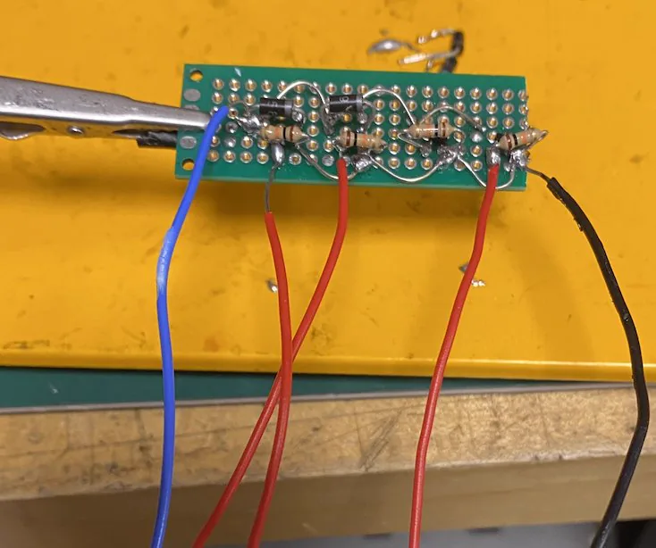
With the frame decided, I moved into research — going through datasheets and comparing options for motors, battery, and the rest of the electronics before ordering anything. For the motor driver circuit specifically, I used CWRU's circuits lab to dig through their parts bins and find N-channel MOSFETs, flyback diodes, and gate resistors that could actually handle the current the motors would pull, instead of just grabbing whatever came up first in a search.
I'd only learned to solder shortly before starting this project, so building the actual board was its own learning curve — and the pick-and-place N-channel MOSFETs were easily the worst part of it. Pick-and-place parts are meant for a reflow oven and a pick-and-place machine, not a soldering iron and a steady hand, so getting clean joints on pads that small without bridging pins or lifting a pad off the board took a lot of retries.
Hand-soldered motor driver board — pick-and-place MOSFETs soldered with an iron
Gyro/Accelerometer Circuit & Wireless Link
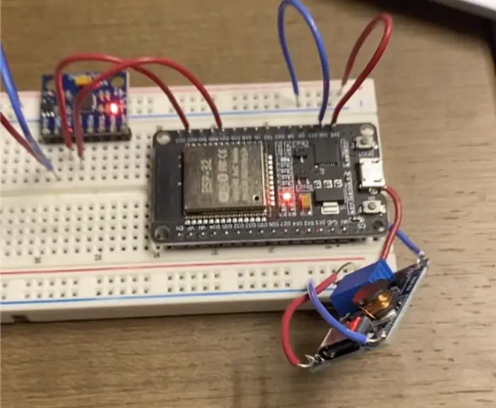
Next was the gyro and accelerometer circuit — the IMU that lets the drone sense its own orientation. Once that was wired up, I connected it wirelessly to a second ESP32 using the ESP-NOW protocol, which lets two ESP32s talk directly to each other over Wi-Fi without a router or any real pairing process, just the receiver's MAC address. I wrote the Arduino firmware to test the link — reading the IMU on one board, packing the data up, and sending it over ESP-NOW to the other — and it worked cleanly on the first real test, no dropped packets or garbage data to chase down.
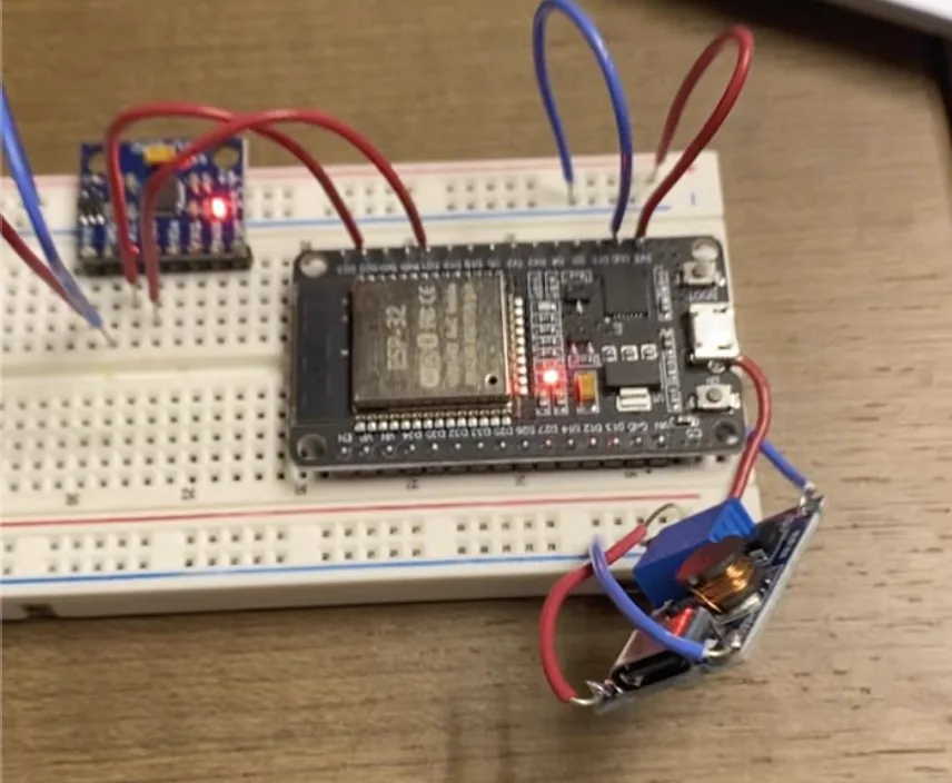
ESP32 flight controller, IMU, and buck converter under bench test
I ended up reusing this same ESP-NOW setup on a later project, the EMG Robotic Hand, to make its control link wireless too — once I had a working wireless firmware pattern, adapting it to a new project was straightforward.
Assembly & Motor Testing
Before assembly, I weighed every component and used the motors' rated thrust to calculate a target thrust-to-weight ratio of about 2:1, which the finished drone ended up hitting almost exactly once everything was actually assembled and weighed for real.
Once the frame, electronics, and motors were all mounted, I went through each motor individually to confirm it spun up cleanly and responded to throttle before ever running all four together. That test caught a problem early: with all four motors spun up at once, the battery's C-rating was too low to supply the current all four motors wanted simultaneously, so the voltage sagged and the motors couldn't get the current they needed. Running the motors one at a time never revealed it, since a single motor's draw was well within what the battery could supply on its own — it only showed up once the draw from all four was added together.
PID Flight Control
For actual flight control I used a PID controller — a control loop that compares the drone's current orientation from the IMU against the orientation it's supposed to hold, and reacts to that error three ways: the proportional term reacts directly to how far off the drone currently is, the integral term accounts for how long the error has been building up so small persistent tilts still get corrected, and the derivative term reacts to how fast the error is changing, which damps the correction instead of letting it overshoot and oscillate. Tuning the three gains by hand meant a lot of short test runs, watching how the props responded to a tilt and adjusting from there.
PID correcting motor speed in response to tilt
Robotics / Biomechanics · Nov 2025
Origins
The finished hand gripping on command
This one came together at a CWRU hackathon, where I met an electrical engineering student at the kickoff and we decided to team up on the spot. The whole build only had a two-day window to begin with, and we lost even more of it when a storm rolled through partway into the second day and the venue cut the event short — so whatever we had working by that point was what we were presenting, no extra runway to fix anything after.
Mechanical Design
We split the mechanical design down the middle — I took the fingers in SolidWorks while my teammate designed the palm. Working in parallel saved time, but it also meant our two halves didn't natively agree with each other: he'd modeled the palm in a different CAD package, and getting his file into something my assembly could actually reference took some back and forth exporting through a neutral format before the two parts would mate up cleanly instead of just sitting next to each other.
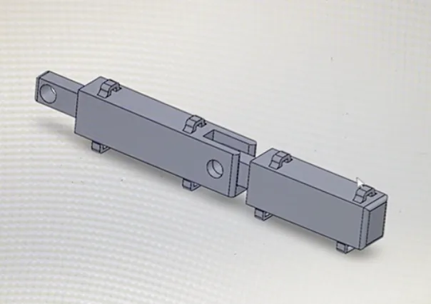
The fingers were also my first real exposure to SolidWorks's mate types beyond just holding parts rigidly in place. Each knuckle uses a hinge mate, which constrains the joint to rotate about a single axis instead of letting it float freely, and getting the fingers to curl the way an actual hand does meant learning how mates stack up to remove degrees of freedom one at a time rather than pinning a part down all at once. It was the first assembly I'd built where the parts were actually supposed to move relative to each other after going together, not just bolt on and stay put.
Finger CAD — hinge-mated knuckle joints
EMG Sensing
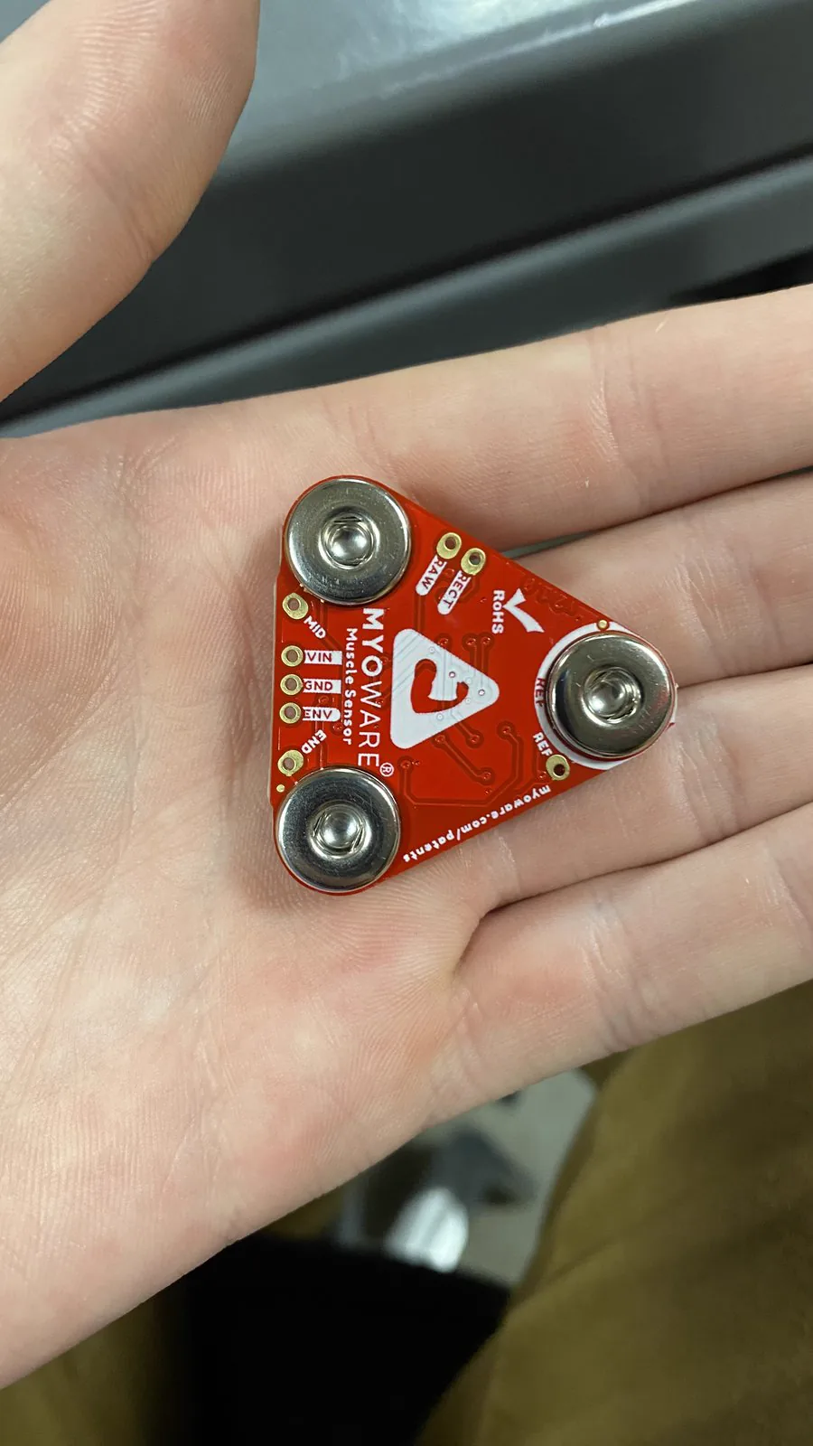
For activation we went with EMG — electromyography — instead of a button or switch, since the point was to have the hand respond to an actual muscle contraction rather than a manual trigger. Flexing a muscle generates a small electrical signal as the muscle fibers fire, and a MyoWare Muscle Sensor picks that signal up through electrodes placed over the forearm and outputs it as an analog voltage that climbs the harder you flex.
MyoWare EMG sensor
I wrote the Arduino firmware to read that raw signal and compare it against a threshold value: cross above it and the hand closes, drop back below it and the hand releases. Getting that threshold right took some trial and error, since the raw signal is noisy and the right cutoff depends a lot on how the electrodes are sitting on the skin that day. That problem was made worse by the fact that we didn't have the proper adhesive gel electrode pads the sensor is meant to be used with — just the bare snap connectors — so getting a usable read meant pressing the sensor directly against the skin and holding it firmly in place, which made the signal noisier and far more sensitive to exact placement than it would've been with real pads.
Wireless Control
Once the sensor was reading cleanly, the next step was getting that signal over to the servos driving the hand without running a wire across the table between two separate boards. I'd already built this same kind of link a few months earlier on the ESP32 Drone project, so instead of re-solving the problem from scratch I reused that pattern here: one ESP32 read the EMG sensor and ran the threshold logic, then sent a simple open/close command over ESP-NOW to a second ESP32 wired to the servos. Testing mostly meant flexing the sensor over and over and watching the servos to make sure the hand opened and closed every single time, not just most of the time — a servo that occasionally missed the signal isn't something you can trust in a live demo.
Presentation & Future
We presented the finished hand to a panel of judges at the end of the hackathon, which given we'd lost part of our already-short build window to the storm meant demoing whatever state it was in the moment the event wrapped. What we built was really just an MVP meant to prove the core idea worked under a heavy time constraint, not a finished product, and there's a lot of room to build on it with more time. The biggest gap is sensor feedback — right now the hand just closes on command with no sense of how hard it's actually gripping, so it can't tell the difference between barely touching something and crushing it. Adding force sensing to the fingertips and feeding that back into the grip logic would be the next real step toward a hand that can actually interact with what it's holding instead of just closing blindly.
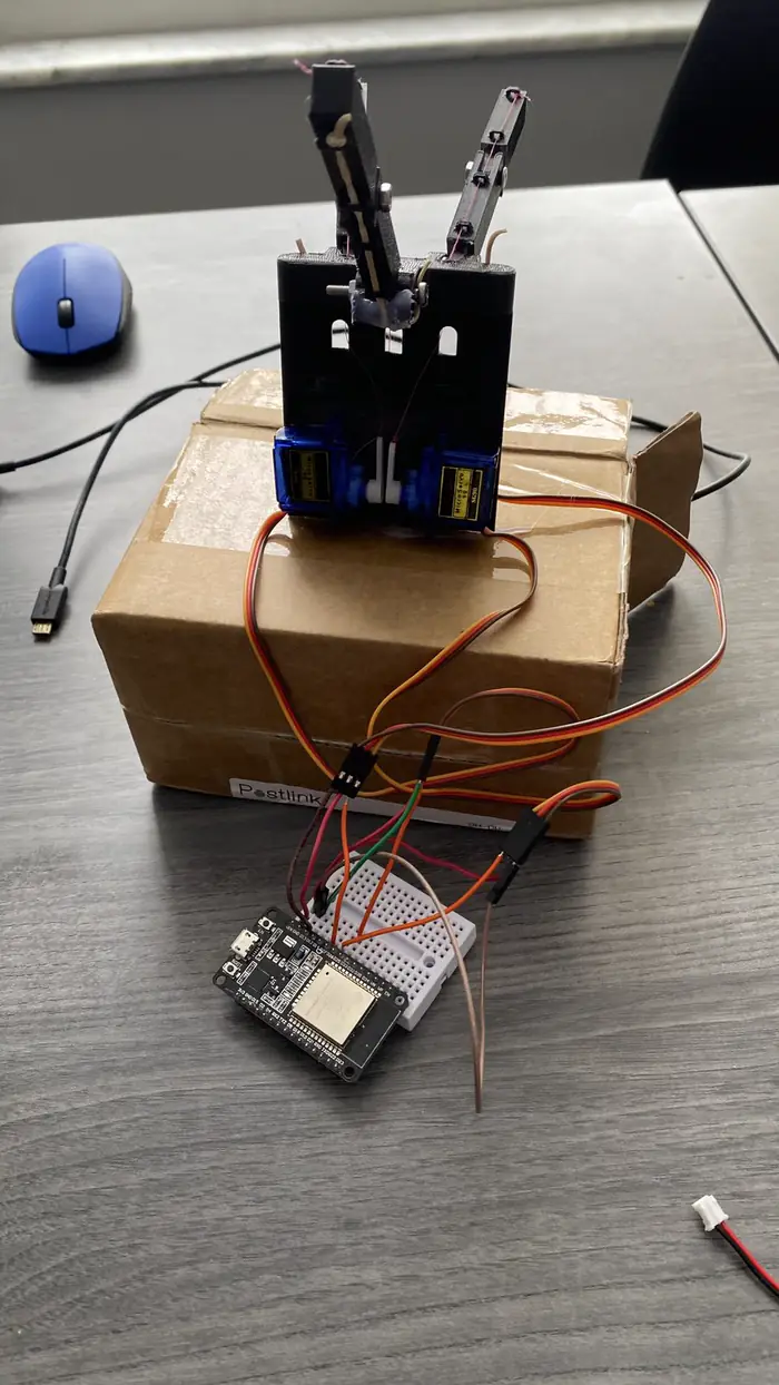
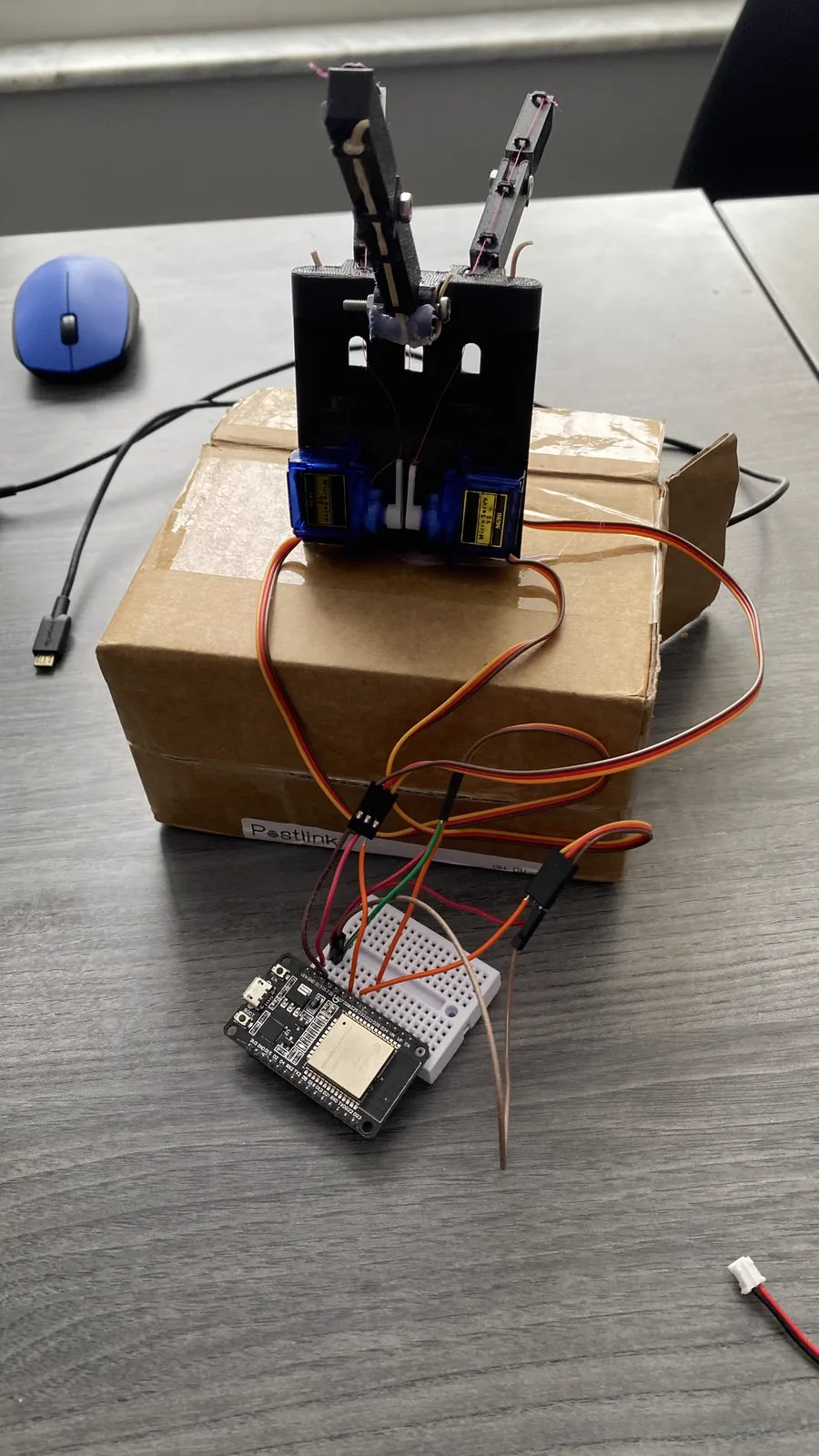
The assembled hand — servos, ESP32, and breadboard wiring
Goes directly to chance.krenzer@gmail.com